TESTING THE CABLE / PIGTAIL
The first component to check if your E-Glide suddenly quits working is the control cable. The Conquest Optima Quad control cable we utilize is a very high quality cable, but if abused, a problem can develop. It has been our observation that the majority of problems we have seen have been incurred after a customer allows another person to ride their powerboard, and the cable is excessively yanked or pulled. The cable end has a MIDI/DIN connector, which locks into the gun bottom, but allows for quick disconnect should pressure be applied. If you fall or jump off of the powerboard, the gun will disconnect from the cable, and the board will stop. Severe pulling on the cable over time can result in a connection break on the end of the cable where it plugs into the gun. The cables are made with stress relief to minimize this problem, but it can happen.
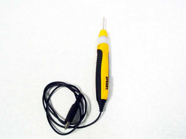
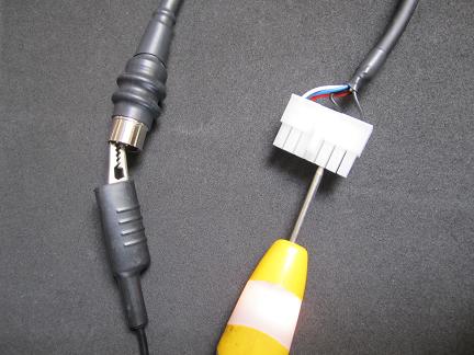
1. The cable wires can be tested easily and quickly with a continuity detector.
2. Lay the powerboard on a work platform upside down, and remove the four allen bolts that hold the electronics in place.
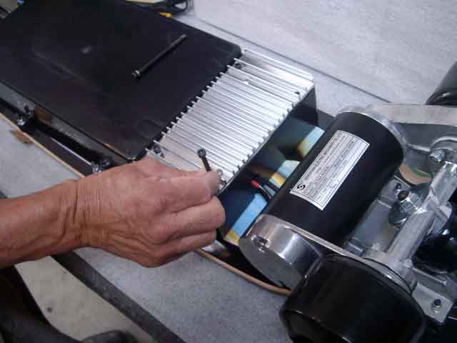
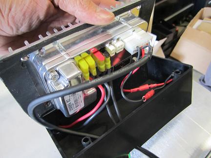
3. Remove the four allen bolts completely from the fin plate before lifting it up. All inputs can be seen once the fin plate is lifted. You will see two wires coming from the battery pack and plugged into red + and black - on the pc board. You will see the two motor wires coming from the motor plugged into the "1" and "2" on the pc board. You will see the cable end, plugged directly into the pc board.
4. First, check each wire in the cable to see if their connected. Unplug the cable from the pc board. Then looking at the plug that connects to your gun, you will see 5 pins. Using the continuity detector test each pin from each end of the cable, from the gun end to the white plug at the other end.

5. Each pin has a wire which runs to the white plug at the p.c. board end of the cable.
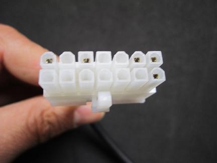
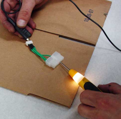
6. Test each pin with the continuity detector in the following sequence: Cable Pin One to-----white connector Pin five Cable Pin Two to-----white connector Pin One Cable Pin Three to-----white connector pin Seven Cable Pin Four to-----white connector Pin Eight Cable Pin Five to-----white connector Pin Two The light should light up each time you make a circuit from the pin to the white plug end. If there is a short in one wire, and the light does not go on, you have found the problem. Also check all pins on the white plug end each time to make sure that the connections aren't crossing.(example: If you test cable pin one and you get a light on pin 5 and 8, then that could be a problem as well.
7. You will place the white plug end up so that the silver tabs show, this is where you will test each wire end with the continuity detector. Test each pin with the continuity detector in the following sequence: Cable Pin One to-----white connector Pin One Cable Pin Two to-----white connector Pin Three Cable Pin Three to-----bullet connector on/off wire (the separate wire coming off of the cable that plugs into the battery wire red + on the pc board) Cable Pin Four to-----white connector Pin Two Cable Pin Five to-----white connector Pin Four. The light should light up each time you make a circuit from the pin to the white plug end. If there is a short in one wire, and the light does not go on, you have found the problem.
This completes the cable check.
